This page is for the no-dimmer MK85 helmet wiring shown in the video. It is intentionally basic: press the trigger and the faceplate opens, press it again and the faceplate closes. The eyes turn on when the helmet is closed and turn off when it opens.
The original bench setup used an Arduino Nano Every or Nano-compatible board, two MG90S style metal gear servos, LED eye panels, and a 4x AA battery holder. The code below is the exact simple sketch to copy into Arduino IDE.
Important: do not power the servos from the Arduino 5V pin. The servo red wires should be powered from the battery positive rail. The Arduino, servos, button, and LEDs must all share ground.
What You Need
| Part | What to use | Notes | Link |
|---|---|---|---|
| Arduino board | Arduino Nano Every or Nano-compatible board | Choose the matching board in Arduino IDE before uploading. | Buy on Amazon |
| Servos | 2x MG90S style metal gear micro servos | Avoid plastic gear SG90 servos for this faceplate mechanism. | Buy on Amazon |
| Eyes | Iron Man LED eye panels or simple LEDs | Simple LEDs need resistors. Bright panels may need a transistor or MOSFET driver. | Buy on Amazon |
| Trigger | Momentary pushbutton | Wires between D2 and GND. No extra resistor needed. | Buy on Amazon |
| Power | 4x AA battery holder | AA cells last longer and handle servos better than AAA cells. | Buy on Amazon |
| Wiring | Jumper wire or hookup wire | Label the servo wires before fitting everything inside the helmet. | Link coming soon |
| Heat shrink | Assorted heat shrink tubing | Use it to protect solder joints and stop shorts inside the helmet. | Buy on Amazon |
No-Dimmer Wiring Diagram
This is the cleaned-up version of the messy bench wiring. Follow the labels first, then use the diagram as a visual check.
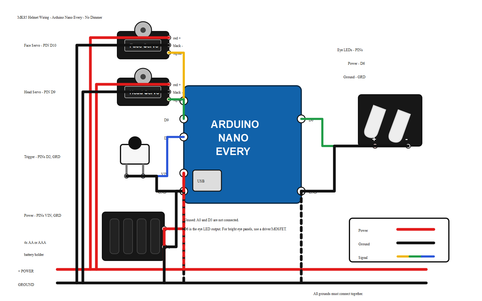
Exact Connections
Arduino IDE Settings
Nano Every
If you are using an older Nano clone: select Arduino Nano, processor ATmega328P. If upload fails, try ATmega328P (Old Bootloader).
Arduino Code
Paste this into a new Arduino IDE sketch and upload it to the Nano. The built-in Servo library is used, so there is no special helmet library to install.
#include <Servo.h>

// MK85 basic Nano controller:
// - 2 servos for the faceplate
// - LED eyes
// - 1 pushbutton to toggle open/closed
// - No dimmer

const byte HEAD_SERVO_PIN = 9;
const byte FACE_SERVO_PIN = 10;
const byte EYE_LED_PIN = 6;
const byte BUTTON_PIN = 2;

// Starting angles from the MK85 servo setup.
// Adjust these in small 1 or 2 degree steps if needed.
const int HEAD_SERVO_OPEN_POS = 20;
const int FACE_SERVO_OPEN_POS = 160;
const int HEAD_SERVO_CLOSE_POS = 160;
const int FACE_SERVO_CLOSE_POS = 20;

const byte EYES_OFF = 0;
const byte EYES_ON = 255;

const int STEP_DELAY_MS = 12;
const unsigned long DEBOUNCE_MS = 60;

Servo headServo;
Servo faceServo;

bool faceplateOpen = false;
bool lastButtonReading = HIGH;
bool stableButtonState = HIGH;
unsigned long lastDebounceTime = 0;

void setup() {
  pinMode(BUTTON_PIN, INPUT_PULLUP);
  pinMode(EYE_LED_PIN, OUTPUT);

  headServo.attach(HEAD_SERVO_PIN);
  faceServo.attach(FACE_SERVO_PIN);

  closeFaceplate();
}

void loop() {
  bool reading = digitalRead(BUTTON_PIN);

  if (reading != lastButtonReading) {
    lastDebounceTime = millis();
  }

  if ((millis() - lastDebounceTime) > DEBOUNCE_MS && reading != stableButtonState) {
    stableButtonState = reading;

    if (stableButtonState == LOW) {
      if (faceplateOpen) {
        closeFaceplate();
      } else {
        openFaceplate();
      }
    }
  }

  lastButtonReading = reading;
}

void openFaceplate() {
  moveServos(
    HEAD_SERVO_CLOSE_POS,
    HEAD_SERVO_OPEN_POS,
    FACE_SERVO_CLOSE_POS,
    FACE_SERVO_OPEN_POS
  );

  setEyes(EYES_OFF);
  faceplateOpen = true;
}

void closeFaceplate() {
  moveServos(
    HEAD_SERVO_OPEN_POS,
    HEAD_SERVO_CLOSE_POS,
    FACE_SERVO_OPEN_POS,
    FACE_SERVO_CLOSE_POS
  );

  setEyes(EYES_ON);
  faceplateOpen = false;
}

void moveServos(int headStart, int headEnd, int faceStart, int faceEnd) {
  int distance = abs(headEnd - headStart);

  for (int i = 0; i <= distance; i++) {
    int headPos = map(i, 0, distance, headStart, headEnd);
    int facePos = map(i, 0, distance, faceStart, faceEnd);

    headServo.write(headPos);
    faceServo.write(facePos);
    delay(STEP_DELAY_MS);
  }
}

void setEyes(byte brightness) {
  analogWrite(EYE_LED_PIN, brightness);
}Expected Behaviour
-
Power on
The servos move to the closed position and the eyes turn on.
-
Press the trigger
The faceplate opens and the eyes turn off.
-
Press the trigger again
The faceplate closes and the eyes turn back on.
Servo Angles
Test the servos before attaching the mechanism to the faceplate. The starting angles are based on the MK85 motorization setup, but every printed helmet and servo horn position is a little different.
Change these four values in small 1 or 2 degree steps until the faceplate opens and closes cleanly:
const int HEAD_SERVO_OPEN_POS = 20;
const int FACE_SERVO_OPEN_POS = 160;
const int HEAD_SERVO_CLOSE_POS = 160;
const int FACE_SERVO_CLOSE_POS = 20;
Tip: if the faceplate moves the wrong way, swap the two servo signal wires on D9 and D10 first. If the same physical servo still refuses to move after swapping, the problem is probably wiring, power, or the servo itself.